

J.F.Drew © 2000-2017


Mobile menus
VK5DJ
VK5DJ synthesiser: a programmable crystal
The project enables connection of either an AD9850 synthesiser module or a si5351a synthesiser module to produce the ‘crystal’ frequency for either a receiver and/or a transmitter.
The AD9850 module is an SSI device and connects to pins 24(DDSclk) , 25 (DDSfq), 26 (DSdata) of the PIC18F2480. Obviously +5V and earth must be provided as well.
The si5351a module is a I2C device and connects to pins 14 (SCL) and 15 (SDA) of the PIC18F2480.
The project expects an I2C keyboard and LCD via a MCP23017 expander chip (diagram 2). This is the same input/output unit as used in my Mk 2 repeater controller.
On applying power a welcome screen is displayed, shortly followed by a line which describes the connected module. If the wrong module is indicated hit either the “*” (selects AD9850) or the “#” (selects si5351a) key to change the module being addressed.
Two frequencies are then written to the screen. “A” is the receive frequency,”B” is the transmit frequency. These are the true frequencies out of the modules, not the final output of the receiver or transmitter. For example if you use a TAIT UHF receiver with a 21.4MHz IF and a desired receive frequency of 442.375MHz then the calculation for the receive frequency is (442.375-21.4)/ 12 = 35.081250. In Hz this is 35081250. Don’t forget the trailing zero or you’ll end up with 3.508125MHz.
Hit the “A” key and then enter 35081250 (frequency entry must be in Hertz) and press “D” to save. As well as setting up the synthesiser this action saves the value into eedata so that next time the unit powers up it will be on 35.08125MHz. If you make a mistake hit the “C” key to cancel and the screen returns to the frequency display screen and discards any values entered.
The transmit frequency is set in a similar way but begun by pressing the “B” key.
What is the advantage of each synthesiser module?
The AD9850 module produces a sine wave at somewhat lower level (1V P/P). If the device is used to replace both the RX and the TX crystals then the output must be shared by the two units – there may be a drive problem requiring the addition of an amplifying stage. The module does have a built in filter to remove the spurii produced by interactions between the crystal frequency and the wanted output. Generally you can expect a cleaner signal from the AD9850. Whenever this module changes frequency the new frequency must be programmed in.
The si5351a module produces a much higher level square wave (3V P/P) which easily drives the receiver or transmitter at the crystal oscillator stage. Its odd harmonics are quite strong though. You’ll need to check that these are not a problem in the transmitter. A low pass filter may be necessary. Another advantage of the si5351a is that it has two (in fact 3) outputs that may be individually programmed. This project uses only outputs 0 and 1. The software in this project programs one to the receive frequency and one to the transmit frequency and then switches the appropriate output stages on or off as required.
How does the unit know when to use the TX or the RX output?
Pin 23 of the PIC is a TTL input. 0V = transmit, +5V = receiver.
It should be wired to any active low transmit port on the controller.
Diagram 1: the synthesiser controller
Diagram 2: Keypad/LCD
The rows and columns on the keypad shown above are provided for illustration only. I wanted the pins 1-8 on the keypad to coincide with pins 1-8 on the MCP23017 for layout reasons. In reality pin 1 of the keypad is not connected to row 1 etc.
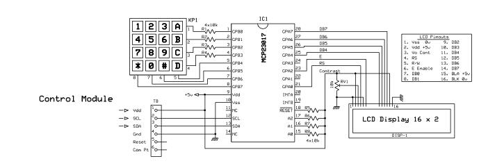
Diagram 3: Test setup on protoboard


Yes, I know it’s ugly but it works as a test setup.
At top is the AD9850 module from eBay, bottom left is the si5351a module, again from eBay. Lower centre is the PIC15F2480.
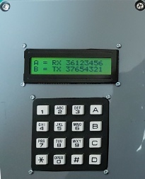
At right is the keypad/lcd display showing RX of 36.123456MHz and TX of 37.654321MHz. This unit communicates with the PIC18F2480 via I2C. You can see the DIN connector to the left. The next task is to put it in a nice die cast box to keep the greeblies both in and out. With the prototype setup there is quite a bit of noise being radiated. The outputs of the modules are reasonably clean. Remember the si5351A does produce a square wave so the odd number harmonics are quite strong. The AD9850 produces a nicer looking wave but if the frequency is too high there is quite a strong product produced higher in frequency. Keep the output below 40MHz and things are fine.

To the left is the DSO showing the sine wave output from the AD9850 while the Spectrum analyser shows the received signal.
The other sigs are outside signals as the SA is running with a piece of wire inserted into the input socket.
| Repeater features |
| Solar version |
| 1750Hz decoder |
| Record and playback |
| Voice interface |
| Micor solution |
| Yagi Calculator |
| RD Contest logger |
| Moon Tracking |
| Orbitron interface |
| PRFCalc |
| TAIT programming |
| Proton Development Suite |
| Old crystals for radios |
| Compound interest |
| Yagi photos |
| Bird proofing |
| Bender |
| VK5DJ downloads |
| VK3UM downloads |
| Site map |