

J.F.Drew © 2000-2017







Mobile menus
VK5DJ
Remote power management of a remote amateur repeater site

The Raspberry Pi 2W is a very inexpensive computer on a board. It has a dual core RP2350 microprocessor,2.4GHz WIFI and Bluetooth 5.2, a 150MHz clock speed, 520kB of SRAM and 4MB of on board flash memory. It has a full speed USB 1.1 host/device controller and 26 GPIO pins.
I have created a mechanism that allows remote monitoring of the voltage and current of both the loads and the solar charger at The Bluff, site of VK5RMG. This repeater system is the centre of the South East Radio Group’s repeater network covering the Lower South East of South Australia and into SW Victoria.
Originally I created a server on the PICO-2W and this performed very well from a home location. However it failed at a remote location due to a characteristic of cell phone towers called CGNAT that effectively prevents an outside IP address from accessing the remote server in the PICO 2W. Another method had to found.
The new method uses a cloud based broker service. The one chosen was io.adafruit.com and involves sending data out from the PICO to an external server, thus avoiding the CGNAT problem. I recommend you examine the Adafruit site facilities.The free service performs very well and updates in < 12 seconds for 6 data points.
Through reading the voltage drop across a shunt resistor we are able to monitor the load (a 2m voice repeater, a 70cm C4FM repeater, three UHF links to other sites, Echolink, and a packet radio system supporting APRS and a Marine tracking system) plus solar.

The shunt to the left is a 30A device that provides 75mV at 30A for detection by the INA226. At 15A it provides 37mV etc. This shunt has negligible impact on the load voltage drop. The load current at VK5RMG currently peaks at about 20ish amps. The INA226 outputs via I2C.
I have created a circuit a little more complex than originally planned as the device is sitting at a remote site and access is difficult. Because the MMBASIC software (or the PICO itself) may fall over after a week or so, I have added a PIC16F1827 as an external watchdog. It works by monitoring a pulse from the PICO and, additionally, has a 1 day timer. The idea is that if the pulse stops because of a program glitch, or if twenty four hours has expired, the PICO is reset by the PIC. This external device is in addition to the internal watchdog and monitoring for loss of the WIFI connection.
Every day the external PIC16F1827 watchdog automatically shuts down and restarts the PICO irrespective of its condition ensuring there is no corruption. The system is unavailable for about 15 seconds at this time. You won’t notice this on io.adafruit.com
Regulated power from a LM7805 powers the PICO that has an onboard 3V3 regulator. It is this 3V3 that powers the entire circuit including the PIC and peripherals. By using 3V3 the problem of matched voltage levels on inputs disappears.
The PICO-2W (or PICO-w) on the right of the circuit does the majority of the work.
The PIC16F1827 or PIC16LF1827 is essentially a watchdog that controls the PICO via its RESET pin 30 (labelled RUN). Click the circuit diagram for a large image.
Click circuit image below for a larger view.
Download Installer for a Windows support program to facilitate setting registers and accuracy.
Download files for PIC16F1827 (or pic 16LF1827) only the hex file is used.
Download connections detail to facilitate soldering
Download gerber files to build PCB
Updated: 5/9/26
The PICO-W or PICO 2W both perform very well in this service.
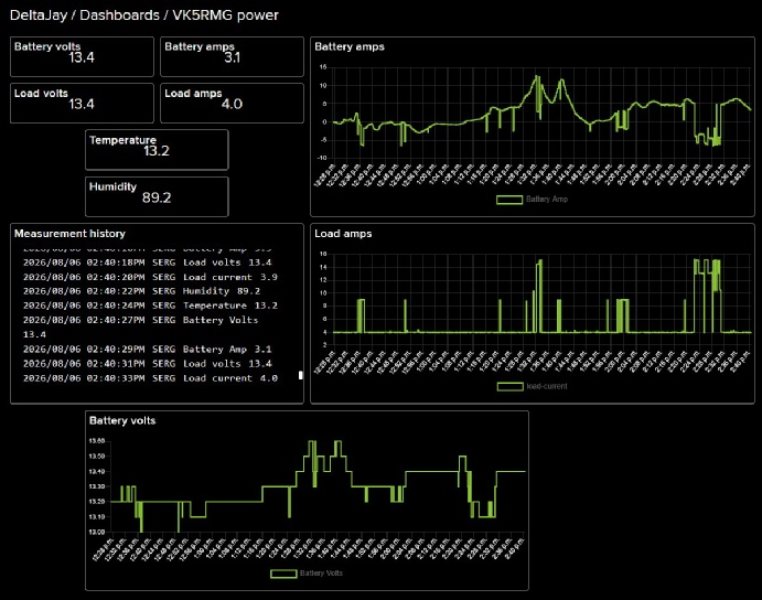
The above image shows how the data looks on my io.adafruit site. In the measurement history the incoming data can be monitored. It updates an item every 2 seconds to fit with the FREE allowance of 30 datapoints per minute. By paying a modest US$10 per month double speed becomes available and generally more options. For me the free version is adequate. NOTE: If you are not logged in to io.adafruit you will not see the data update.
There is a learning curve. I provide the following program for the PICO but I have “XXX” out the critical key information to protect the privacy of my site. Download “SERGada.bas” the file to upload to the PICO-2w. You’ll need to sort out the io.adafruit site, create feeds and a dashboard. Marvellous what having to work things out does to your understanding. Your first step is to create a login to io.adafruit.com then create the feeds and connect them to the incoming data.
For starters, to program the PICO you’ll need to upload the operating system into the PICO. Download the OS (WebMiteRP2350V6.03.01RC25.uf2) and follow the instructions on Geoff’s site. Note this file is for the PICO 2W. If you use the cheaper PICO -W you’ll need to track down that file (WebMiteRP2040V6.03.01RC25.uf2) on geoffg.net
Download a copy of Terra Term 5 and with the PICO plugged in to a USB socket you should be able to monitor what is going on. Now you need to do some reading - Geoff’s watering controller explains some of the moves once you have typed ctrl<C>“ to obtain the “>” prompt. Next, type OPTION wifi “SSID”,”Password” (your router), set OPTION TCP server port 80, and OPTION Telnet console on. Note the sample in the above download has fixed values for testing. Comment these lines 130,139,147,155,163,170 and remove the “ ’ “ in the lines above to activate encoders.
Sensors:
I have added a Temperature/Humidity Sensor (DHT22) as a plug in option. This needs to be mounted external to the box for obvious reasons.
I use two INA226 devices to
(1) detect Battery voltage and current
(2) detect Load voltage and current
The system is wired such that the battery current is negative if the load exceeds the power from the solar.

| Repeater features |
| Solar version |
| 1750Hz decoder |
| Record and playback |
| Voice interface |
| Micor solution |
| Yagi Calculator |
| RD Contest logger |
| Moon Tracking |
| Orbitron interface |
| PRFCalc |
| TAIT programming |
| Proton Development Suite |
| Old crystals for radios |
| Compound interest |
| Yagi photos |
| Bird proofing |
| Bender |
| VK5DJ downloads |
| VK3UM downloads |
| Site map |